Pulsar Pixel Raster Line Display in Periodic Logic
I built this mechanism over the course of around a year, all told. The kernal of the works came from the head-on collision of two LWSSs. A regular p120 LWSS stream moving right collides with a perforated p120 LWSS stream moving left. A leftward LWSS being present causes a collision; one absent will cause the next possible collision to occur 30 cells to the right. This is what I call the 'Draw Back', and is used in 3 different ways throughout the mechanism. Mark Niemic's one sided 3 glider pulsar synthesis sealed the deal. After a little experimentation I found a single glider/pulsar imploding reaction that erases both. This latter is viable at p30. LIF file zipped and attached below.
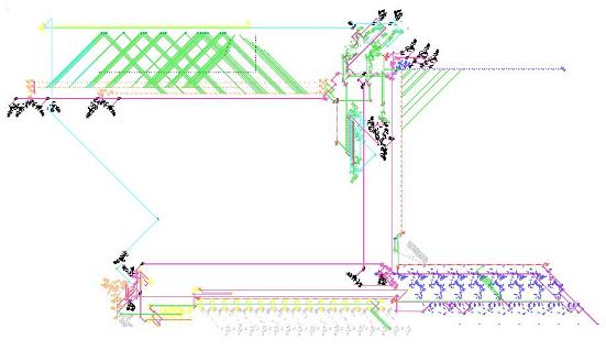
- PulsarPixelDisplay2a.JPG (23.99 KiB) Viewed 70634 times
Shown above is a colorized screen shot of the mechanism. Proceeding counter clockwise from lower left are the following components:
There are two p1920n One-Shot Latches shown in Black (as are all p1920n one-shots). The lower of the two is the p5760 master clock, initially set. Above this is a p1920x18 one-shot to delay the erase process. Just to the right of the master clock is the p5760 Data Transfer Clock, shown in Yellow.
Next, in Orange, is the Increment/Decrement Register, an adaptation of David Buckingham's adder.
Just below the register, in Gray, is a p60 to p30 converter, which delivers the requisite 4 bits of data to the ondinal converter as LWSSs at p30.
Next, in Yellow, is the 4 bit Binary to Ordinal Converter. It incorporates a latch and gap 8 reaction from Paul Rendell's Turing Machine, and features a nifty 4on-4off gun from Dean Hickerson's collection.
Continuing rightward along the bottom, in Gray, are the Bit Map ROM cells, 64 bit adaptations of the memory cells in Rendell's Turing Machine, triggered by the ordinal.
At bottom right, in Blue, are the 8 Display Cells, again a 64 bit warped version of Paul Rendell's memory cell. Once loaded, these cells are triggered by MWSSs delivered by the print control logic. When triggered, 8 bits of data are scraped from the 'top' of each cell, erased within the cell, and the remaining 56 bits are transfered forward, so that at the end of 8 raster line print cycles, the cells are empty and ready for reload. Data is collected by a leftward moving p30 LWSS stream, and converted to positive logic upward at the left end. The 240 cell horizontal spacing of the cells is no accident. Given the right moving MWSS trigger, and left moving data, a 720 generation gap (360 cells @ c/2) exists between one 8 bit p30 data set and the next, the requisite amount to allow the p30 to p120 converter, shown in Gray above the data cells, to perform autonomously and deliver contiguous data @ p120.
The Raster Line Timing Structure, in Black throughout the remainder of the mechanism, consists of a number of varying heisenburps, reflectors, counters, and p1920n one-shots that allow a single signal to synchronize the activities of printing the raster lines, resetting the modules, retriggering further raster line printing, and lastly retriggering the p5760 master clock one-shot. All control signal paths are shown in Violet. Data paths are shown in Green, and Erase/Reset paths in Cyan.
Data leaving the p30>p120 converter perforates the upward LWSS stream of the Modulator, shown with a Red vertical axis and the Blue horizontal axis forming the 4th quadrant orientation of the device. Three p120 LWSS streams (one down, one up, and one leftward) converge in this fashion:
the up/down pair of LWSSs collide to form two gliders; one is eaten, and the 2nd reflects up right.
The up right glider deletes a LWSS from the leftward stream. If a data bit is present, an upward LWSS is absent, and the next possible up/down collision occurs 30 cells lower. This lowers the path of the next possible glider, and in so doing, allows TWO LWSSs to escape leftward at the output. The first of the pair is heisenburped backward and the resultant glider deletes the second LWSS. This arrangement is desired because, in the print carriage, a pixel not printed calls for a single LWSS absent to draw the head on collisions rightward, whereas a printed pixel calls for LWSSs present to create gliders for the pulsar synthesis AND LWSSs absent to create the drawback for the next pixel. Output of the modulator is collected by a downward LWSS stream of length to support all 64 possible printed pixels (i.e. a burst of 128 LWSSs). This results in an inverted data stream; the collecting Gun is shown in Red.
Left of this, in Green, are the two Steppers, triggered by the raster timing to produce output streams just in advance of arriving data from the modulator. The right stepper handles the two up right gliders in the pulsar synthesis, and the left the up left glider. This leading stepper burst, along with the Step Delay, in Green @ center, provide the necessary shifts in the overall data streams to accomodate successively lower raster lines. Finally, the data streams are followed by a burst of 16 bits @ p120 from the Post Stepper gun, also in Green to the right of the step delay. These bits ensure that the print carriage collisions arrive at the right end carriage stops regardless of which raster line is being printed. So then, the full data streams consist of Steppers + Modulated Data + Post Steppers. The two final streams arrive at the print carriage and are in inverse logic.
The Print Carriage, in Orange near top left, provides for the up left (bottom rail) and up right (top two rails) glider streams that react in Mark Niemic's pulsar pixel forming synthesis. Three pairs of opposed p120 LWSS guns provide for the reactions. Initially, the glider forming collisions occur at the left hand carriage return stop, with no gliders released. Data arrives at right in inverted logic such that a data bit present deletes a leftward moving LWSS causing the next possible collision point to draw back 30 cells rightward. A data bit absent leaves a LWSS to collide and produce a pair of gliders (one eaten) should the print position be in between the carriage return and end stops. So, then, raster lines are formed left to right, prepositioned by the stepping mechanisms for vertical, and create identical data sets and post steps for all three rails.
After eight raster line cycles are initiated, a LWSS is fired to set the master clock one shot, loading data for the next character line. Once these eight raster lines near completion, again the set pulse fires, setting the master, which then (by virtue of being divided by two) does the following:
1) starts a new load cycle,
2) increments/decrements the data register,
3) initiates an erase cycle.
The Erase Mechanism, at top left in Yellow, consists of a p30 MWSS gun and blocking stream, a p30n blocking stream at the right end with companion p480 gun, and 79 MWSS heisenburps. An arriving erase pulse releases a burst of 16 MWSSs through the burps, yielding adequate gliders to implode a fully displayed 64x16 pixel matrix. At right one of the MWSSs escapes the blocking stream, and is reflected up to reset the steppers for the next two character lines. Also, noteworthy is that after the data for each 16th raster line passes the step delay, the step delay is reset using a nifty LWSS/MWSS eater synthesis by Mark Niemic.
And that's pretty much it. The device, as delivered will load and print two character lines (the hexadecimal numeric character set), first in ascending order, will erase, and then repeat the process in descending order, and repeat the whole process ad nauseum. A complete two pass run of ascending and descending display takes just under a million generations.
Enjoy,
triller
The attachment PulsarPixelDisplayZIP.zip is no longer available


