Seamless Penrose Kite and Dart images

A forum for topics that don't fit elsewhere. Introduce yourselves to other members of the forums, discuss how your name evolves when written out in the Game of Life, or just tell us how you found it. Forum rules still apply.
Post Reply
User avatar
pcallahan
Posts: 924
Joined: April 26th, 2013, 1:04 pm

Seamless Penrose Kite and Dart images

Post by pcallahan » August 26th, 2025, 11:23 pm

This was something I wanted to do for a while. It's pretty easy to make perfect seamless periodic tiles using AI art. Some of the engines support it, and just prompting for seamless often does a decent job (usually not quite right). If you're a perfectionist, you can cut up the tiles to move the matching interior to the boundaries and fill the new interior with infill.

However, I want seamless Penrose tiles. The boundaries have to match according to Penrose rules and not introduce obvious artifacts like a kaleidoscope reflection. I did this by generating as much as I could fit near the sides of kites and darts, and using AI to infill the interior. These came out pretty well. I am not going to be a perfectionist today but I might work a little harder later.
image1-3-8-5-3.jpg
image1-3-8-5-3.jpg (141.6 KiB) Viewed 1824 times
The arrows indicate the usual way to line up sides of adjacent tiles.

Here are two symmetric layouts using these. You can see that symmetries jump out where corners meet but it's still a natural texture overall. This could be used for decorative purposes if you didn't want the Penrose tiles to be obvious. There is still a lot of geometry that is hard to miss.
tiling1.jpg
tiling1.jpg (515.77 KiB) Viewed 1824 times
tiling2.jpg
tiling2.jpg (339.6 KiB) Viewed 1824 times

User avatar
pcallahan
Posts: 924
Joined: April 26th, 2013, 1:04 pm

Re: Seamless Penrose Kite and Dart images

Post by pcallahan » August 29th, 2025, 1:03 am

Another idea. Contours that cross perpendicular to matching boundaries. The reason this is useful is to preserve continuity and avoid kaleidoscope effects in adjacency tiles (assuming you don't want a kaleidoscope effect). I did this in Inkscape but took a systematic approach to constructing Bezier curves, using equal-length line segments normal to the boundary intersection to place the control point.
g23-5.png
g23-5.png (1.02 MiB) Viewed 1779 times

User avatar
pcallahan
Posts: 924
Joined: April 26th, 2013, 1:04 pm

Re: Seamless Penrose Kite and Dart images

Post by pcallahan » August 31st, 2025, 1:18 am

Another approach is to forget about continuity and use natural contours. These tiles are based on actual floor planks. They repeat but there is enough variety that it's hard to see. This could be cut out of wood and inlaid.
g17.png
g17.png (400.71 KiB) Viewed 1745 times

User avatar
pcallahan
Posts: 924
Joined: April 26th, 2013, 1:04 pm

Re: Seamless Penrose Kite and Dart images

Post by pcallahan » September 1st, 2025, 1:14 am

expanded it a bit
penrose0831.png
penrose0831.png (3.82 MiB) Viewed 1727 times

User avatar
pcallahan
Posts: 924
Joined: April 26th, 2013, 1:04 pm

Re: Seamless Penrose Kite and Dart images

Post by pcallahan » September 2nd, 2025, 10:05 am

One more and I think I'm done with the woodgrain look. I still have some seamless tiles to explore.
penrose0901.jpg
penrose0901.jpg (2.52 MiB) Viewed 1708 times

User avatar
pcallahan
Posts: 924
Joined: April 26th, 2013, 1:04 pm

Re: Seamless Penrose Kite and Dart images

Post by pcallahan » September 5th, 2025, 1:27 am

Yet another way of decorating the tiles. Find the in centers of the component triangles and connect those with arcs that meet smoothly at boundaries. My original goal was to carve up the tiles to get a better sense of how to make them seamless. I'm not sure this will help, but another thing this does is create recognizable, distinct shapes around all the ways of placing incident corners.
bafkreiezoz6mczrhfofnakijxmtpfgzwo56wzfijqkr2y474bh3rtdtvf4.jpg
bafkreiezoz6mczrhfofnakijxmtpfgzwo56wzfijqkr2y474bh3rtdtvf4.jpg (290.5 KiB) Viewed 1678 times

User avatar
pcallahan
Posts: 924
Joined: April 26th, 2013, 1:04 pm

Re: Seamless Penrose Kite and Dart images

Post by pcallahan » September 28th, 2025, 4:20 pm

I am pretty sure I read about someone doing this already: making a Voronoi diagram of the points where corners meet in a Penrose tiling, but it's the first time I tried it. One thing I noticed (unless I'm mistaken) is that once you've done two deflations, you can just copy the Voronoi boundaries the rest of the way. The reason is that the Delaunay triangulation can be constructed by splitting the kites and dates into triangles and then flipping the boundary between adjacent darts.

Starting with this half dart and half kite:
g3.png
g3.png (140.03 KiB) Viewed 1623 times
you can make larger patches of tiling such as:
g11.png
g11.png (1.75 MiB) Viewed 1623 times
and
g15.png
g15.png (1.1 MiB) Viewed 1623 times
Unlike the previous tile marking, this does not produce unique contours for each way of placing incident corners. For instance, the Voronoi cell at the center of an ace depends on context, and one of them (a trapezoid) is identical to a different corner placement.

Note that I did not have to script any of this but could work out the geometry in Inkscape as well as carry out deflation using copy-paste.

User avatar
pcallahan
Posts: 924
Joined: April 26th, 2013, 1:04 pm

Re: Seamless Penrose Kite and Dart images

Post by pcallahan » October 1st, 2025, 11:11 am

Somewhat annoyingly, rhombs result in a simpler Voronoi diagram, i.e. one that works with unit tiles without any deflation, "annoyingly," because I like kites and darts better, but maybe rhombs are really the canonical form (or their Robinson tile equivalents).

This Voronoi diagram could be done with natural stones and would not obviously be a Penrose tiling to those who didn't look carefully.
g30.png
g30.png (916.17 KiB) Viewed 1582 times
Oh, what the heck, here it is AI enhanced.
topviewofa-2658082692-14_58_59.png
topviewofa-2658082692-14_58_59.png (1.78 MiB) Viewed 1582 times

User avatar
pcallahan
Posts: 924
Joined: April 26th, 2013, 1:04 pm

Re: Seamless Penrose Kite and Dart images

Post by pcallahan » October 3rd, 2025, 6:29 pm

One more variation of seamless rocks. This arrangement is arbitrary but I plan to do one based on a voronoi diagram.
bafkreic3ouhdrscrfas6dz436xp5irl2m3mx352cfnonzsvrhp74ktctmq.jpg
bafkreic3ouhdrscrfas6dz436xp5irl2m3mx352cfnonzsvrhp74ktctmq.jpg (676.56 KiB) Viewed 1475 times

User avatar
pcallahan
Posts: 924
Joined: April 26th, 2013, 1:04 pm

Re: Seamless Penrose Kite and Dart images

Post by pcallahan » October 5th, 2025, 1:58 pm

Voronoi diagram as bumps on 3D printed kites and darts. There is an extra Voronoi point in the center of each kite corresponding to the rhomb tessellation.
20251005_105032.jpg
20251005_105032.jpg (2.04 MiB) Viewed 1443 times

User avatar
pcallahan
Posts: 924
Joined: April 26th, 2013, 1:04 pm

Re: Seamless Penrose Kite and Dart images

Post by pcallahan » October 5th, 2025, 10:09 pm

If anyone wants to try to print this, here's a link to the model: https://www.printables.com/model/143605 ... -and-surfa

I liked how this backlit macro photo came out, and I added the Delaunay and Voronoi edges. While the tiles are kites and darts, the Delaunay triangulation is based on a rhomb tiling.
image1.png
image1.png (1.22 MiB) Viewed 1396 times

User avatar
pcallahan
Posts: 924
Joined: April 26th, 2013, 1:04 pm

Re: Seamless Penrose Kite and Dart images

Post by pcallahan » October 25th, 2025, 12:34 pm

The result is more coherent if you print separate snap parts for each of the Voronoi "cobblestones." See https://www.printables.com/model/145060 ... estone-sur

They can also be printed in multiple colors or painted for a simulated stone look. You could cut real stones into shape too for part of a courtyard.
The pieces:
20251023_083831.jpg
20251023_083831.jpg (1.05 MiB) Viewed 1308 times
A patch with kites and darts hidden underneath:
20251023_083351.jpg
20251023_083351.jpg (2.95 MiB) Viewed 1308 times
A patch using two colors:
20251024_195510.jpg
20251024_195510.jpg (1.47 MiB) Viewed 1308 times

User avatar
pcallahan
Posts: 924
Joined: April 26th, 2013, 1:04 pm

Re: Seamless Penrose Kite and Dart images

Post by pcallahan » October 26th, 2025, 1:52 pm

Back to seamless kit and dart tiles. This shows a way of partitioning tiles into boundary triangles along long and short edges, leaving interior quadrilaterals in the tiles. I did this by trial and error in Inkscape, but if time permits I might try to set up an equation. Maybe the math works out nicely.
text8-7.png
text8-7.png (372.41 KiB) Viewed 1293 times

User avatar
pcallahan
Posts: 924
Joined: April 26th, 2013, 1:04 pm

Re: Seamless Penrose Kite and Dart images

Post by pcallahan » October 28th, 2025, 12:30 am

A digitally altered photo with a little interior artistry to smooth out transitions. It uses the boundary regions from the previous posting.
image1.jpg
image1.jpg (3.19 MiB) Viewed 1268 times

User avatar
pcallahan
Posts: 924
Joined: April 26th, 2013, 1:04 pm

Re: Seamless Penrose Kite and Dart images

Post by pcallahan » December 21st, 2025, 2:46 am

Not really anything new, but here is a Voronoi diagram with the rhomb tiling superimposed. I have assigned a distinct color to each of the 7 distinct Voronoi cells.
path1.png
path1.png (1.32 MiB) Viewed 1181 times

User avatar
pcallahan
Posts: 924
Joined: April 26th, 2013, 1:04 pm

Re: Seamless Penrose Kite and Dart images

Post by pcallahan » December 21st, 2025, 2:41 pm

Asking Google Gemini to turn the layout it a jeweled brooch.
Gemini_Generated_Image_93vejq93vejq93ve.png
Gemini_Generated_Image_93vejq93vejq93ve.png (2.03 MiB) Viewed 1163 times
It did a pretty good job (a bit garish I admit). Here's the starting point, without the rhombs.
g1.png
g1.png (863.86 KiB) Viewed 1163 times

User avatar
pcallahan
Posts: 924
Joined: April 26th, 2013, 1:04 pm

Re: Seamless Penrose Kite and Dart images

Post by pcallahan » December 21st, 2025, 3:21 pm

More fun with another picture. I used GIMP to create the perspective view before asking Gemini.
path2.png
path2.png (452.24 KiB) Viewed 1161 times
Gemini_Generated_Image_f83e5wf83e5wf83e.png
Gemini_Generated_Image_f83e5wf83e5wf83e.png (2.25 MiB) Viewed 1161 times
Gemini_Generated_Image_t95vy5t95vy5t95v.png
Gemini_Generated_Image_t95vy5t95vy5t95v.png (2.19 MiB) Viewed 1161 times

User avatar
pcallahan
Posts: 924
Joined: April 26th, 2013, 1:04 pm

Re: Seamless Penrose Kite and Dart images

Post by pcallahan » April 17th, 2026, 2:01 pm

Modular system for Penrose Voronoi suncatchers. The final result here is clear resin but you could swirl in some color or even cast colored tesserae separately, which I have done, and place them in the mold.

The basic pieces are Penrose kite and darts inflated to show some Voronoi cells and split at those boundaries. The pentagon fills in the corners. The wall pieces are there to hold in the silicone for casting a mold. I haven't enumerated all possible boundaries. I am working on that and will probably exclude some. I have 3D-printed all of them in PLA.

The trick to removing 3D-print artifacts is to coat the inside of the mold with more silicone after curing and cure a second time. This covers the top texture and also gives it a lens-like meniscus. Geometry, technology, and physics all went into this.

Final suncatcher:
20260417_085831.jpg
20260417_085831.jpg (3.94 MiB) Viewed 811 times
Pieces:
20260417_093210.jpg
20260417_093210.jpg (2.56 MiB) Viewed 811 times
Assembly to fill, silicone model, final resin cast:
20260417_105504.jpg
20260417_105504.jpg (3.36 MiB) Viewed 811 times

User avatar
pcallahan
Posts: 924
Joined: April 26th, 2013, 1:04 pm

Re: Seamless Penrose Kite and Dart images

Post by pcallahan » April 22nd, 2026, 10:49 am

More art than math but here I go. First a new suncatcher based on center darts instead of kites. I assembled the PLA master like a jigsaw puzzle, made a silicone mold, assembled colored tesserae in that mold and poured clear resin to hold it together. I have another mold for casting tesserae, arranged to make 5 of each color. This is a little sloppy looking and could be smoothed out with another pour of clear. Right now the resin droplets and the 3D print artifacts both show up.
20260420_071729.jpg
20260420_071729.jpg (1.33 MiB) Viewed 759 times
Next is my most creative mold modification. After curing the silicone mold, I pour a coat of silicone mixed with eggshells ground in a coffee grinder. This leaves a bumpy mold surface that inverts to a pitted surface on the clear resin cast. It is closest I have been able to get so far in simulating a stone surface. With opaque resin and a matte coating, it might even be convincing as stone.

Two views. It looks different depending on how it catches the light, and unfortunately my phone camera "corrects" for some of the best effects.
20260420_183632 (1).jpg
20260420_183632 (1).jpg (1.05 MiB) Viewed 759 times
20260420_183444.jpg
20260420_183444.jpg (1.07 MiB) Viewed 759 times
A forensic analysis could probably uncover its origin as a 3D print, but I don't think it's obvious to the casual observer.

User avatar
pcallahan
Posts: 924
Joined: April 26th, 2013, 1:04 pm

Re: Seamless Penrose Kite and Dart images

Post by pcallahan » May 5th, 2026, 11:30 am

Preview of a modular system for making "cobblestone" molds based on the Voronoi diagram of Penrose tiles. I need to write up a howto and post to Printables, but it's a bit more involved than others.

These are the thirteen pieces including kites, darts, pentagon corner fittings, and walls to hold silicone. Some are blank so you can extend to a wall
20260429_205055.jpg
20260429_205055.jpg (1.37 MiB) Viewed 645 times
.

Making a mold and removing it.
20260504_225713.jpg
20260504_225713.jpg (1.04 MiB) Viewed 645 times
20260504_225945.jpg
20260504_225945.jpg (1.67 MiB) Viewed 645 times
Last edited by pcallahan on May 5th, 2026, 11:37 am, edited 1 time in total.

User avatar
pcallahan
Posts: 924
Joined: April 26th, 2013, 1:04 pm

Re: Seamless Penrose Kite and Dart images

Post by pcallahan » May 5th, 2026, 11:36 am

A little explanation. Here is how kites and dart pieces fit together.
g6.png
g6.png (170.03 KiB) Viewed 645 times
There is no way to assign a regular pentagon to a single piece because of five-fold corners, so that's kept separate.

This uses a different set of walls but illustrates the full workflow from PLA pieces to resin cast. I smoothed out the mold with a second coating of silicone to cover 3D print artifacts. The resulting meniscus also gives the cells a lens-like effect.
20260417_105504 (1).jpg
20260417_105504 (1).jpg (2.62 MiB) Viewed 645 times

User avatar
pcallahan
Posts: 924
Joined: April 26th, 2013, 1:04 pm

Re: Seamless Penrose Kite and Dart images

Post by pcallahan » May 8th, 2026, 2:38 pm

I finally did a write-up of the modular system.
https://www.printables.com/model/169740 ... ilicone-mo

If you don't feel like clicking, here's a Claude best-effort conversion to phpBB (I need to try this for other posts, since I have never really gotten the hang of posting here), though it looks like it "fixed" some of my phrasing too.

Once again, these are the actual printable pieces.
20260429_205055.jpg
20260429_205055.jpg (1.96 MiB) Viewed 589 times
Modular Penrose Cobblestone System for Silicone Molds
By Paul Callahan

Summary
A set of tiles that fit together like a jigsaw puzzle into frames that can be filled with silicone to make resin molds.

Overview
This is a more ambitious follow-up to my Penrose Voronoi suncatcher. Instead of providing just one design, it is a set of pieces that fit together like a jigsaw puzzle, including surrounding walls so it can be filled with silicone. It's based on a Penrose rhomb tiling — one of an infinite set of aperiodic planar tessellations by fat and skinny rhombuses. Using their vertices as points in a planar point set, you can construct a Voronoi diagram, giving a layout that looks like a natural stone patio. The Voronoi cells have a more organic appearance and don't immediately read as math or geometry the way the raw Penrose tiling does.

The Tiles
While individual cells can be assembled on their own, they can also be grouped into clusters assigned to larger tiles for easier assembly. This can continue indefinitely, since Penrose tilings are defined in terms of inflation/deflation rules. The base tile shapes are kites and darts. (Penrose tilings can be converted between rhombs and kite/dart form using a local transformation.)

When tiles are placed together, the adjacent corners leave pentagonal gaps. Since there's no way to assign a pentagon to a single tile while preserving the five-fold symmetric corners, these are provided as separate one-cell pentagon pieces.

Wall pieces are also included that fit around the perimeter of any assembly — matching either the long sides of kite and dart tiles, or two successive short sides on the same tile. Flat extension pieces let you push any assembly outward to where you can attach walls.

How to Use with Silicone
Supplies needed: two-part silicone rubber, two-part epoxy resin, and optionally resin dye in various colors.

Piecewise frames will always leak to some degree, though this is self-limiting as silicone builds up. Silicone may also form thin ribbons inside unintended gaps. To address the ribbon problem, a lip is included around the top of each tile to constrain the silicone — any ribbon that forms in a crack can usually be peeled off carefully at the perforation.

There are two approaches to deal with leaking:
  1. Seal the mold first with a washable material such as Elmer's school glue.
  2. Use the silicone itself as a progressive seal.
The second approach works well. Here's the recommended process:
  1. Pour a small initial amount of silicone and use it to coat the frame — brush it on or tilt the frame to let gravity distribute it. The goal is to get silicone into the tile gaps and wall gaps to form a dam, not a perfect seal.
  2. Let the coated frame cure for a few hours until tacky.
  3. Pour the remaining silicone. Some spillage may still occur, but most will stay in the mold.
If you pour everything in at once, you'll get more spillage and possible ribbons to trim, but the mold will still function.

Applications
Once you have your silicone mold, several finished pieces are possible:
  • Colorful suncatcher — Use the included tessera mold frames to cast individual colored resin pieces, then assemble them and pour clear resin over the top to hold everything together.
  • Clear cast — Pour clear resin directly into the mold. Applying a second silicone coating inside the mold before casting gives a smoother surface finish.
  • Textured cobblestone look — Add texture and color to the mold, then use a resin/eggshell mixture to simulate mortar between the stones.
Model Files

Code: Select all

kite_raised.stl
dart_raised.stl
pentagon_raised.stl
wall_1.stl
wall_2.stl
wall_3.stl
wall_4.stl
pentagon_1_wall.stl
pentagon_2_walls.stl
pentagon_3_walls.stl
kite_flat.stl
dart_flat.stl
pentagon_flat.stl
optional-tesserare-mold-1.stl
optional-tesserare-mold-2.stl
optional-tesserare-mold-3.stl
License
This work is licensed under a Creative Commons Attribution-ShareAlike 4.0 International License. Commercial use and remixing are permitted with attribution.

User avatar
pcallahan
Posts: 924
Joined: April 26th, 2013, 1:04 pm

Re: Seamless Penrose Kite and Dart images

Post by pcallahan » Yesterday, 12:02 am

Here's something I have thought about for a while and had been putting off until I realized that I could Claude-code the whole thing without too much effort. I already had code to generate the vertices of a Penrose rhomb tiling. I only needed to reconstruct the edges based on distance so I could do a 2-coloring. Unfortunately, you can't just color acute and obtuse angles, since this will result in adjacencies between equal colors.

Anyway, the idea is to color the vertices as positive and negative charges so that edges are always between charges of opposite sign. After that, calculate electrostatic potential and show the equipotential lines. I tried both 2d and 3d potential (log and 1/d respectively). I think 3d looks better even though the points are in the plane so I went with that.
equipotential_penrose_3d.png
equipotential_penrose_3d.png (389.27 KiB) Viewed 46 times
Here's the code. I haven't really read it carefully but it works OK. It includes a smaller set of points for testing, but any mesh will work if edges are length 1/phi. Claude applies a quadratic all-pairs algorithm rather than building an efficient structure to find close neighbors

Code: Select all

import math
import numpy as np
from PIL import Image, ImageDraw
from collections import deque

# Parameters
# Usage: script.py [k [size [--pts file.txt]]]
import argparse, sys
parser = argparse.ArgumentParser()
parser.add_argument("k",    nargs="?", type=int, default=5,   help="number of equipotential lines")
parser.add_argument("size", nargs="?", type=int, default=800, help="image size in pixels")
parser.add_argument("--pts", metavar="FILE", default=None,    help="text file with x y coords, one per line")
parser.add_argument("--2d", dest="two_d", action="store_true", help="use 2D log potential (ln r) instead of 3D (1/r)")
parser.add_argument("--edges", action="store_true", help="draw adjacency edges of the unit-distance graph")
args = parser.parse_args()

k    = args.k
size = args.size
r_min = 0.01    # clamp radius to avoid singularity
margin = 0.5    # margin around point cloud bounding box

# ------------------------------------------------------------
# All vertices of the Penrose rhomb tiling (unit edge length).
# We build the unit-distance graph and 2-colour it by BFS,
# then assign negative charge to one colour class and positive
# to the other so the total charge remains zero.
# ------------------------------------------------------------

all_pts = [
    # ---- originally labelled "black" (51 pts) ----
    (0.000000, 0.000000), (1.000000, 0.000000), (0.500000, -0.363271),
    (0.309017, -0.951057), (-0.500000, -0.363271), (-0.690983, -0.951057),
    (-0.500000, -1.538842), (0.000000, -1.902113), (0.500000, -1.538842),
    (1.000000, -1.902113), (0.190983, -2.489898), (0.690983, -2.853170),
    (1.309017, -2.853170), (1.809017, -2.489898), (1.618034, -1.902113),
    (2.118034, -1.538842), (2.427051, -2.489898), (2.927051, -2.126627),
    (3.118034, -1.538842), (2.927051, -0.951057), (2.309017, -0.951057),
    (2.118034, -0.363271), (3.118034, -0.363271), (2.927051, 0.224514),
    (2.427051, 0.587785), (1.809017, 0.587785), (1.618034, -0.000000),
    (1.309017, 0.951057), (0.690983, 0.951057), (0.190983, 0.587785),
    (-0.809017, 0.587785), (-0.000000, 1.175571), (0.500000, 1.538842),
    (1.118034, 1.538842), (2.118034, 1.538842), (2.927051, 0.951057),
    (3.427051, 0.587785), (3.618034, -0.000000), (3.927051, -0.951057),
    (3.618034, -1.902113), (3.427051, -2.489898), (2.927051, -2.853170),
    (2.118034, -3.440955), (1.118034, -3.440955), (0.500000, -3.440955),
    (0.000000, -3.077684), (-0.809017, -2.489898), (-1.118034, -1.538842),
    (-1.309017, -0.951057), (-1.118034, -0.363271), (1.309017, -0.951057),
    # ---- originally labelled "red" (25 pts) ----
    (-0.190983, -0.587785), (-0.190983, -1.314328), (0.500000, -2.265384),
    (1.190983, -2.489898), (2.309017, -2.126627), (2.736068, -1.538842),
    (2.736068, -0.363271), (2.309017, 0.224514), (1.190983, 0.587785),
    (0.500000, 0.363271), (-0.190983, 0.587785), (1.618034, 1.175571),
    (2.309017, 0.951057), (3.427051, -0.587785), (3.427051, -1.314328),
    (2.309017, -2.853170), (1.618034, -3.077684), (-0.190983, -2.489898),
    (-0.618034, -1.902113), (-0.618034, -0.000000), (1.118034, -0.363271),
    (0.690983, -0.951057), (1.118034, -1.538842), (1.809017, -1.314328),
    (1.809017, -0.587785),
]

if args.pts:
    with open(args.pts) as f:
        all_pts = [tuple(float(v) for v in line.split()) for line in f if line.strip()]
    print(f"Loaded {len(all_pts)} points from {args.pts}")

pts_arr = np.array(all_pts)
n = len(pts_arr)

# Build unit-distance adjacency (edge length = 1/phi ≈ 0.618, tolerance 0.05)
EDGE_LEN = 2 / (1 + np.sqrt(5))   # 1/phi = phi - 1 ≈ 0.61803
adj = [[] for _ in range(n)]
for i in range(n):
    for j in range(i + 1, n):
        if abs(np.linalg.norm(pts_arr[i] - pts_arr[j]) - EDGE_LEN) < 0.05:
            adj[i].append(j)
            adj[j].append(i)

# BFS 2-colouring (graph is bipartite — verified)
color = [-1] * n
color[0] = 0
q = deque([0])
while q:
    node = q.popleft()
    for nb in adj[node]:
        if color[nb] == -1:
            color[nb] = 1 - color[node]
            q.append(nb)

group_A_idx = [i for i in range(n) if color[i] == 0]
group_B_idx = [i for i in range(n) if color[i] == 1]
group_A = [all_pts[i] for i in group_A_idx]  # negative (red dots)
group_B = [all_pts[i] for i in group_B_idx]  # positive (blue dots)

# Remap adjacency to positions-array ordering (group_A first, then group_B)
old_to_new = {old_i: new_i for new_i, old_i in enumerate(group_A_idx + group_B_idx)}
adj_final = [[] for _ in range(n)]
for old_i, neighbors in enumerate(adj):
    new_i = old_to_new[old_i]
    adj_final[new_i] = [old_to_new[nb] for nb in neighbors]

n_A = len(group_A)   # 36
n_B = len(group_B)   # 40
q_A = -float(n_B) / n_A   # ≈ -1.1111, keeps total charge = 0
q_B = 1.0

positions = np.array(group_A + group_B)
charges   = np.array([q_A] * n_A + [q_B] * n_B)

print(f"Group A (negative): {n_A} x {q_A:.4f} = {n_A * q_A:.4f}")
print(f"Group B (positive): {n_B} x {q_B:.4f} = {n_B * q_B:.4f}")
print(f"Total charge: {charges.sum():.6f}")

# Bounding box + margin
x_lo = positions[:, 0].min() - margin
x_hi = positions[:, 0].max() + margin
y_lo = positions[:, 1].min() - margin
y_hi = positions[:, 1].max() + margin

xs = np.linspace(x_lo, x_hi, size)
ys = np.linspace(y_lo, y_hi, size)
X, Y = np.meshgrid(xs, ys)

# Compute potential: 2D log potential sum q_i*ln(r) or 3D Coulomb sum q_i/r
V = np.zeros((size, size))
for i in range(len(positions)):
    dx = X - positions[i, 0]
    dy = Y - positions[i, 1]
    r  = np.maximum(np.sqrt(dx**2 + dy**2), r_min)
    V += charges[i] * (np.log(r) if args.two_d else 1.0 / r)

print(f"Potential: {'2D logarithmic' if args.two_d else '3D Coulomb (1/r)'}")

# Equipotential levels via percentile clipping
v_lo  = np.percentile(V, 2)
v_hi  = np.percentile(V, 98)
v_rng = max(abs(v_lo), abs(v_hi))
levels = np.linspace(-v_rng, v_rng, k + 2)[1:-1]

print(f"Potential range (2nd–98th pct): {v_lo:.3f} to {v_hi:.3f}")
print(f"Equipotential levels: {[f'{l:.3f}' for l in levels]}")

# Render: white background, sign-change contour detection
img    = Image.new("RGB", (size, size), "white")
pixels = img.load()
line_color = (20, 20, 20)

for level in levels:
    shifted = V - level
    iy, ix = np.where(shifted[:-1, :] * shifted[1:, :] < 0)
    for y, x in zip(iy, ix):
        pixels[x, y] = line_color
    iy, ix = np.where(shifted[:, :-1] * shifted[:, 1:] < 0)
    for y, x in zip(iy, ix):
        pixels[x, y] = line_color

# Draw charge positions
draw  = ImageDraw.Draw(img)
r_dot = size/300

def to_pixel(px, py):
    ix = int((px - x_lo) / (x_hi - x_lo) * size)
    iy = int((py - y_lo) / (y_hi - y_lo) * size)
    return ix, iy

# Draw adjacency edges (drawn first so dots render on top)
if args.edges:
    edge_color = (180, 180, 180)
    for i in range(len(positions)):
        for j in adj_final[i]:
            if j > i:
                x1, y1 = to_pixel(*positions[i])
                x2, y2 = to_pixel(*positions[j])
                draw.line([x1, y1, x2, y2], fill=edge_color, width=int(math.ceil(size/600)))

for i, (px, py) in enumerate(positions):
    cx, cy = to_pixel(px, py)
    # Colour by graph 2-colouring class, not by charge sign
    dot_color = (200, 30, 30) if i < n_A else (30, 30, 200)   # red = group A, blue = group B
    draw.ellipse([cx - r_dot, cy - r_dot, cx + r_dot, cy + r_dot],
                 fill=dot_color, outline=(0, 0, 0))

out_path = 'equipotential_penrose_3d.png'
img.save(out_path)
img.show()
print(f"Saved to {out_path}")
Same image without rhombus edges.
equipotential_penrose_3d.png
equipotential_penrose_3d.png (292.92 KiB) Viewed 46 times

User avatar
pcallahan
Posts: 924
Joined: April 26th, 2013, 1:04 pm

Re: Seamless Penrose Kite and Dart images

Post by pcallahan » Yesterday, 11:16 am

A few updates. After trying to make a 3d-printable surface, I realized the electrostatic potential was the wrong kind of terrain and switched to Gaussian drop-off and then exponential, which Claude helpfully suggested as Yukawa potential.

Code: Select all

import math
import numpy as np
from PIL import Image, ImageDraw
from collections import deque

# Parameters
# Usage: script.py [k [size [--pts file.txt]]]
import argparse, sys
parser = argparse.ArgumentParser()
parser.add_argument("k",    nargs="?", type=int, default=5,   help="number of equipotential lines")
parser.add_argument("size", nargs="?", type=int, default=800, help="image size in pixels")
parser.add_argument("--pts", metavar="FILE", default=None,    help="text file with x y coords, one per line")
parser.add_argument("--2d", dest="two_d", action="store_true", help="use 2D log potential (ln r) instead of 3D (1/r)")
parser.add_argument("--gaussian", metavar="SIGMA", type=float, default=None,
                    help="use Gaussian potential exp(-r²/2σ²) with given sigma instead of electrostatic")
parser.add_argument("--yukawa", metavar="LAMBDA", type=float, default=None,
                    help="use exponential potential exp(-r/λ) with given decay length")
parser.add_argument("--edges", action="store_true", help="draw adjacency edges of the unit-distance graph")
parser.add_argument("--heatmap", action="store_true", help="render potential as a colour heatmap instead of contour lines")
parser.add_argument("--no-dots", dest="no_dots", action="store_true", help="do not draw charge position dots")
parser.add_argument("--bw", action="store_true", help="greyscale heightmap (black=min, white=max) for 3D rendering")
args = parser.parse_args()

k    = args.k
size = args.size
r_min = 0.01    # clamp radius to avoid singularity
margin = 0.5    # margin around point cloud bounding box

# ------------------------------------------------------------
# All vertices of the Penrose rhomb tiling (unit edge length).
# We build the unit-distance graph and 2-colour it by BFS,
# then assign negative charge to one colour class and positive
# to the other so the total charge remains zero.
# ------------------------------------------------------------

all_pts = [
    # ---- originally labelled "black" (51 pts) ----
    (0.000000, 0.000000), (1.000000, 0.000000), (0.500000, -0.363271),
    (0.309017, -0.951057), (-0.500000, -0.363271), (-0.690983, -0.951057),
    (-0.500000, -1.538842), (0.000000, -1.902113), (0.500000, -1.538842),
    (1.000000, -1.902113), (0.190983, -2.489898), (0.690983, -2.853170),
    (1.309017, -2.853170), (1.809017, -2.489898), (1.618034, -1.902113),
    (2.118034, -1.538842), (2.427051, -2.489898), (2.927051, -2.126627),
    (3.118034, -1.538842), (2.927051, -0.951057), (2.309017, -0.951057),
    (2.118034, -0.363271), (3.118034, -0.363271), (2.927051, 0.224514),
    (2.427051, 0.587785), (1.809017, 0.587785), (1.618034, -0.000000),
    (1.309017, 0.951057), (0.690983, 0.951057), (0.190983, 0.587785),
    (-0.809017, 0.587785), (-0.000000, 1.175571), (0.500000, 1.538842),
    (1.118034, 1.538842), (2.118034, 1.538842), (2.927051, 0.951057),
    (3.427051, 0.587785), (3.618034, -0.000000), (3.927051, -0.951057),
    (3.618034, -1.902113), (3.427051, -2.489898), (2.927051, -2.853170),
    (2.118034, -3.440955), (1.118034, -3.440955), (0.500000, -3.440955),
    (0.000000, -3.077684), (-0.809017, -2.489898), (-1.118034, -1.538842),
    (-1.309017, -0.951057), (-1.118034, -0.363271), (1.309017, -0.951057),
    # ---- originally labelled "red" (25 pts) ----
    (-0.190983, -0.587785), (-0.190983, -1.314328), (0.500000, -2.265384),
    (1.190983, -2.489898), (2.309017, -2.126627), (2.736068, -1.538842),
    (2.736068, -0.363271), (2.309017, 0.224514), (1.190983, 0.587785),
    (0.500000, 0.363271), (-0.190983, 0.587785), (1.618034, 1.175571),
    (2.309017, 0.951057), (3.427051, -0.587785), (3.427051, -1.314328),
    (2.309017, -2.853170), (1.618034, -3.077684), (-0.190983, -2.489898),
    (-0.618034, -1.902113), (-0.618034, -0.000000), (1.118034, -0.363271),
    (0.690983, -0.951057), (1.118034, -1.538842), (1.809017, -1.314328),
    (1.809017, -0.587785),
]

if args.pts:
    with open(args.pts) as f:
        all_pts = [tuple(float(v) for v in line.split()) for line in f if line.strip()]
    print(f"Loaded {len(all_pts)} points from {args.pts}")

pts_arr = np.array(all_pts)
n = len(pts_arr)

# Build unit-distance adjacency (edge length = 1/phi ≈ 0.618, tolerance 0.05)
EDGE_LEN = 2 / (1 + np.sqrt(5))   # 1/phi = phi - 1 ≈ 0.61803
adj = [[] for _ in range(n)]
for i in range(n):
    for j in range(i + 1, n):
        if abs(np.linalg.norm(pts_arr[i] - pts_arr[j]) - EDGE_LEN) < 0.05:
            adj[i].append(j)
            adj[j].append(i)

# BFS 2-colouring (graph is bipartite — verified)
color = [-1] * n
color[0] = 0
q = deque([0])
while q:
    node = q.popleft()
    for nb in adj[node]:
        if color[nb] == -1:
            color[nb] = 1 - color[node]
            q.append(nb)

group_A_idx = [i for i in range(n) if color[i] == 0]
group_B_idx = [i for i in range(n) if color[i] == 1]
group_A = [all_pts[i] for i in group_A_idx]  # negative (red dots)
group_B = [all_pts[i] for i in group_B_idx]  # positive (blue dots)

# Remap adjacency to positions-array ordering (group_A first, then group_B)
old_to_new = {old_i: new_i for new_i, old_i in enumerate(group_A_idx + group_B_idx)}
adj_final = [[] for _ in range(n)]
for old_i, neighbors in enumerate(adj):
    new_i = old_to_new[old_i]
    adj_final[new_i] = [old_to_new[nb] for nb in neighbors]

n_A = len(group_A)   # 36
n_B = len(group_B)   # 40
q_A = -float(n_B) / n_A   # ≈ -1.1111, keeps total charge = 0
q_B = 1.0

positions = np.array(group_A + group_B)
charges   = np.array([q_A] * n_A + [q_B] * n_B)

print(f"Group A (negative): {n_A} x {q_A:.4f} = {n_A * q_A:.4f}")
print(f"Group B (positive): {n_B} x {q_B:.4f} = {n_B * q_B:.4f}")
print(f"Total charge: {charges.sum():.6f}")

# Bounding box + margin
x_lo = positions[:, 0].min() - margin
x_hi = positions[:, 0].max() + margin
y_lo = positions[:, 1].min() - margin
y_hi = positions[:, 1].max() + margin

xs = np.linspace(x_lo, x_hi, size)
ys = np.linspace(y_lo, y_hi, size)
X, Y = np.meshgrid(xs, ys)

# Compute potential
V = np.zeros((size, size))
for i in range(len(positions)):
    dx = X - positions[i, 0]
    dy = Y - positions[i, 1]
    r2 = dx**2 + dy**2
    if args.gaussian is not None:
        s2 = args.gaussian ** 2
        kernel = np.exp(-r2 / (2 * s2))
    elif args.yukawa is not None:
        kernel = np.exp(-np.sqrt(r2) / args.yukawa)
    elif args.two_d:
        kernel = np.log(np.maximum(np.sqrt(r2), r_min))
    else:
        kernel = 1.0 / np.maximum(np.sqrt(r2), r_min)
    V += charges[i] * kernel

mode = (f"Gaussian σ={args.gaussian}" if args.gaussian is not None
        else f"Yukawa λ={args.yukawa}" if args.yukawa is not None
        else "2D logarithmic" if args.two_d else "3D Coulomb (1/r)")
print(f"Potential: {mode}")

# Potential range: full extent for Gaussian, percentile clip otherwise
if args.gaussian is not None or args.yukawa is not None:
    v_lo = V.min()
    v_hi = V.max()
else:
    v_lo = np.percentile(V, 2)
    v_hi = np.percentile(V, 98)
v_rng = max(abs(v_lo), abs(v_hi))
levels = np.linspace(-v_rng, v_rng, k + 2)[1:-1]

print(f"Potential range: {v_lo:.3f} to {v_hi:.3f}")
print(f"Equipotential levels: {[f'{l:.3f}' for l in levels]}")

# Render
if args.bw:
    # Greyscale heightmap: black=min, white=max
    V_clip = np.clip(V, v_lo, v_hi)
    t = (V_clip - v_lo) / (v_hi - v_lo)   # 0..1
    grey = (t * 255).astype(np.uint8)
    img = Image.fromarray(grey, "L").convert("RGB")
elif args.heatmap:
    # Diverging heatmap: blue (negative) → white (zero) → red (positive)
    V_clip = np.clip(V, v_lo, v_hi)
    t = (V_clip - v_lo) / (v_hi - v_lo)   # 0..1
    # blue→white for t<0.5, white→red for t>0.5
    R = np.where(t < 0.5, t * 2, 1.0)
    G = np.where(t < 0.5, t * 2, 2.0 - t * 2)
    B = np.where(t < 0.5, 1.0, 2.0 - t * 2)
    rgb = np.stack([R, G, B], axis=-1)
    img = Image.fromarray((rgb * 255).astype(np.uint8), "RGB")
else:
    img    = Image.new("RGB", (size, size), "white")
    pixels = img.load()
    line_color = (20, 20, 20)

    for level in levels:
        shifted = V - level
        iy, ix = np.where(shifted[:-1, :] * shifted[1:, :] < 0)
        for y, x in zip(iy, ix):
            pixels[x, y] = line_color
        iy, ix = np.where(shifted[:, :-1] * shifted[:, 1:] < 0)
        for y, x in zip(iy, ix):
            pixels[x, y] = line_color

# Draw charge positions
draw  = ImageDraw.Draw(img)
r_dot = size/300

def to_pixel(px, py):
    ix = int((px - x_lo) / (x_hi - x_lo) * size)
    iy = int((py - y_lo) / (y_hi - y_lo) * size)
    return ix, iy

# Draw adjacency edges (drawn first so dots render on top)
if args.edges:
    edge_color = (180, 180, 180)
    for i in range(len(positions)):
        for j in adj_final[i]:
            if j > i:
                x1, y1 = to_pixel(*positions[i])
                x2, y2 = to_pixel(*positions[j])
                draw.line([x1, y1, x2, y2], fill=edge_color, width=1)

if not args.no_dots:
    for i, (px, py) in enumerate(positions):
        cx, cy = to_pixel(px, py)
        # Colour by graph 2-colouring class, not by charge sign
        dot_color = (200, 30, 30) if i < n_A else (30, 30, 200)   # red = group A, blue = group B
        draw.ellipse([cx - r_dot, cy - r_dot, cx + r_dot, cy + r_dot],
                     fill=dot_color, outline=(0, 0, 0))

out_path = 'equipotential_penrose_3d.png'
img.save(out_path)
img.show()
print(f"Saved to {out_path}")
Update: You might wonder why I'm doing the 2-coloring. There's not a clear justification except I initially imagined this as electrostatic charge and wanted it to zero-out at a distance. But with faster attenuation, there's not as much need. I'll try that later. Another idea is to have positive potential and take max, not sum. In that case, I believe the voronoi boundaries will show up naturally. I'll try these out later today.

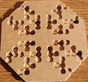
Here are vertices expanded out 5 levels.
pen5.txt
(8.97 KiB) Not downloaded yet
Run with arguments 11 3000 --pts pen5.txt --edges --yukawa 0.3
pen5lines.PNG
pen5lines.PNG (649.59 KiB) Viewed 26 times
Run with arguments 11 3000 --pts pen5.txt --no-dots --yukawa 0.3 --heatmap
pen5heatmap.PNG
pen5heatmap.PNG (2.04 MiB) Viewed 26 times

Post Reply